Professional Anchor Bolt Design Software
Design concrete anchors faster with WebStructural's powerful anchor bolt designer. ACI 318 Chapter 17 compliant. Try it free today.
Start Designing NowWhat is WebStructural Anchor Bolt Designer?
WebStructural Anchor Bolt Designer is a professional concrete anchor design tool built specifically for designing cast-in-place and post-installed anchors in concrete. Whether you're a structural engineer, connection designer, or student, our anchor bolt designer makes complex anchor calculations simple and accurate.
Built on proven structural analysis methods and fully compliant with ACI 318 Chapter 17 design provisions, WebStructural provides accurate, code-compliant anchor designs you can trust. Design single anchors or anchor groups with tension, shear, or combined loading - all right in your browser with no installation required.
Why Choose WebStructural Anchor Bolt Designer?
Instant Analysis
Real-time design checks for all failure modes. See tension, shear, and combined load results instantly.
ACI 318 Compliant
Full compliance with ACI 318 Chapter 17 anchor design provisions. All failure modes checked automatically.
Complete Failure Mode Checks
Automated checks for steel rupture, concrete breakout, pullout, side-face blowout, and pryout.
Cloud-Based
No installation needed. Access your designs anywhere, anytime from any device.
Anchor Groups
Design single anchors or complex anchor groups with automatic group effect calculations.
Made for Engineers
Built by structural engineers, for structural engineers. Intuitive workflow that matches your process.
Comprehensive Anchor Bolt Design Capabilities
Tension Design Checks
- Steel strength in tension (ACI 17.6.1)
- Concrete breakout strength (ACI 17.6.2)
- Pullout strength (ACI 17.6.3)
- Side-face blowout (ACI 17.6.4)
- Anchor group effects and edge distance factors
- Supplementary reinforcement considerations
Shear Design Checks
- Steel strength in shear (ACI 17.7.1)
- Concrete breakout strength (ACI 17.7.2)
- Concrete pryout strength (ACI 17.7.3)
- Edge distance and spacing effects
- Shear load direction considerations
- Lever arm and pryout mechanisms
Combined Loading
- Tension and shear interaction (ACI 17.8)
- Three-point interaction diagrams
- Conservative linear interaction checks
- Multiple load combination analysis
- Critical load case identification
- Capacity ratio reporting
Anchor Group Configuration
- Single anchor or anchor groups (up to 12 anchors)
- Custom anchor patterns and spacing
- Automatic group effect calculations
- Edge distance verification
- Overlapping failure cone detection
- Load distribution in groups
Material & Geometry Options
- Multiple concrete strengths (2500-10000 psi)
- Standard anchor bolt sizes (1/4" - 2")
- Custom embedment depths
- Cracked and uncracked concrete conditions
- Normal weight and lightweight concrete
- Various anchor materials and grades
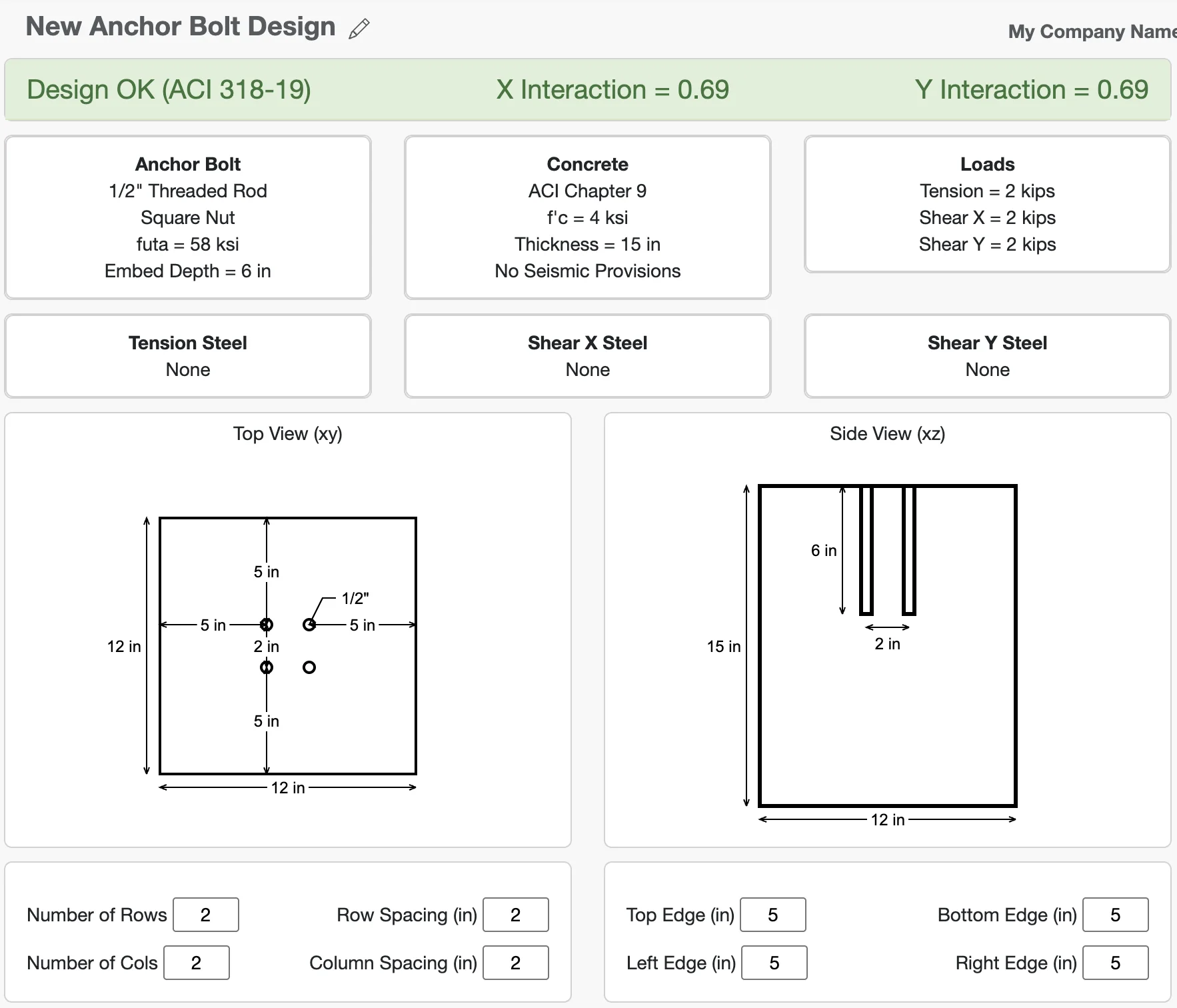
Design Reports & Visualization
- 3D anchor group visualization
- Plan view with edge distances
- Detailed calculation steps for all checks
- Capacity ratio summaries by failure mode
- Critical load case identification
- Print-ready documentation
How Anchor Bolt Designer Works
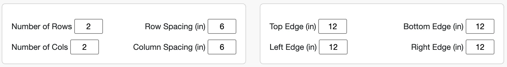
1. Configure Geometry
Start by defining your concrete member geometry and anchor bolt layout. Specify the slab dimensions, edge distances, anchor spacing, and embedment depth. The app provides a 3D visualization and plan view so you can verify your configuration before analysis.
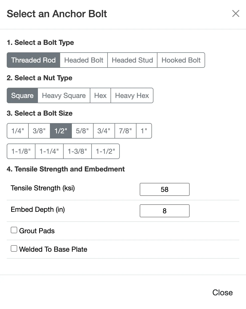
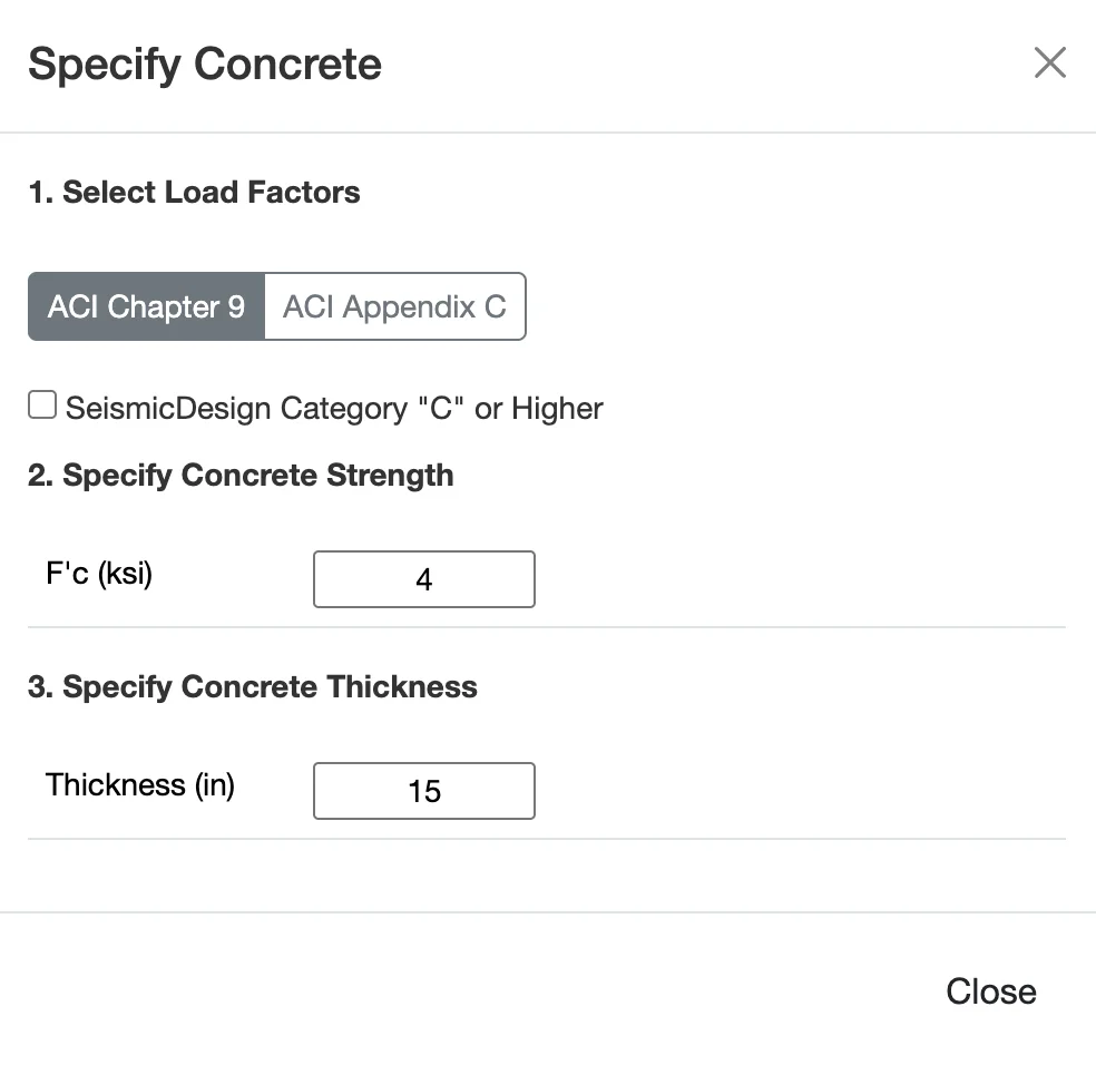
2. Set Materials & Anchor Properties
Select your concrete strength and specify whether the concrete is cracked or uncracked. Choose the anchor bolt diameter and material grade. These properties directly affect the capacity calculations for all failure modes.
3. Apply Loads
Enter your design loads - tension and shear forces. Organize loads by load case (dead, live, wind, seismic, etc.) and the app automatically applies LRFD load combinations per ACI 318 and ASCE 7. Specify whether seismic design requirements apply.
4. Review All Failure Modes
WebStructural instantly performs all required design checks per ACI 318 Chapter 17. See capacity ratios for steel rupture, concrete breakout, pullout, side-face blowout, pryout, and combined loading. All calculations shown step-by-step in detailed reports.
Comprehensive Failure Mode Analysis
Steel Strength (Tension & Shear)
Verifies that the anchor bolt itself has adequate strength to resist applied loads. Checks the steel cross-sectional area and material grade against tension and shear demands. This is often the simplest check but can govern for small diameter anchors.
- Nominal tensile strength (futa × Ase)
- Nominal shear strength (0.6 × futa × Ase)
- Reduction factors (φ)
- Effective cross-sectional area
Concrete Breakout (Tension & Shear)
Evaluates the concrete cone or wedge failure around the anchor. Embedment depth, edge distance, and anchor spacing all affect the breakout capacity. Often the governing failure mode for shallow embedments or anchors near edges.
- Projected concrete failure area (ANc, AVc)
- Edge distance and spacing modification factors
- Concrete strength and cracking condition
- Anchor group effects
Pullout Strength
Checks the anchor's resistance to being pulled straight out of the concrete without causing a concrete cone failure. Depends on the anchor head bearing area and embedment depth. Critical for headed anchors and mechanical expansion anchors.
- Bearing area of anchor head
- Concrete compressive strength
- Embedment depth effects
- Anchor type considerations
Side-Face Blowout
Verifies that anchors near a concrete edge won't cause a local failure where the concrete breaks out toward the side face. Critical when anchors are close to edges with insufficient edge distance. Particularly important for headed anchors in thin members.
- Edge distance perpendicular to load
- Anchor head dimensions
- Member thickness effects
- Multiple anchor considerations
Pryout Strength
Evaluates a shear-related failure mode where the anchor acts as a lever, causing a tensile concrete breakout on the back side of the anchor. Important for short, stiff anchors subjected to shear loads. Based on the concrete breakout strength in tension.
- Relationship to concrete breakout in tension
- Anchor stiffness and embedment
- Shear load eccentricity
- Conservative capacity factor (kcp)
Combined Tension & Shear
When anchors are subjected to both tension and shear simultaneously, an interaction check is required. WebStructural evaluates the three-point interaction equation per ACI 318, ensuring the combined loading doesn't exceed the anchor's capacity.
- Tension and shear interaction equation
- Capacity reduction for combined loading
- Critical load combination identification
- Interaction diagram visualization
Built for Connection Design Professionals
Structural Engineers
Save hours on anchor design with instant calculations and ACI 318 compliant results. Perfect for base plate connections, equipment anchorage, and edge details.
- Fast connection design
- All failure modes checked automatically
- Code-compliant calculations
- Save and manage projects
Students & Educators
Learn anchor design with interactive visual feedback. Understand how geometry, embedment, and edge distance affect each failure mode.
- Visual failure mode illustrations
- Step-by-step calculations
- Comprehensive tutorials
- Free tier available
Contractors & Fabricators
Quickly verify anchor bolt sizes and embedments on the job. Simple interface with easy-to-understand capacity ratios.
- Easy-to-read results
- Quick anchor checks
- Mobile-friendly design
- No installation needed
Technical Specifications
Design Standards
- Concrete Anchors: ACI 318 Chapter 17
- Loads: ASCE 7 load combinations
- Method: LRFD and strength design
- Seismic: ACI 318 seismic provisions (Appendix D)
Failure Modes Checked
- Steel strength (tension and shear)
- Concrete breakout (tension and shear)
- Pullout strength
- Side-face blowout
- Pryout strength
- Combined tension and shear interaction
Supported Configurations
- Anchors: Single anchor or groups (up to 12)
- Bolt Sizes: 1/4" to 2" diameter
- Concrete Strengths: 2500-10000 psi
- Conditions: Cracked and uncracked concrete
Platform
- Web-based (Chrome, Firefox, Safari, Edge)
- No installation required
- Cloud storage for projects
- Responsive design for mobile and tablet
Ready to Design Better Anchor Bolts?
Join thousands of engineers who trust WebStructural for fast, accurate anchor design. Start your free trial today - no credit card required.